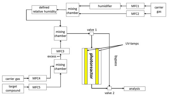
Figure 1: Schematic overview of the experimental set-up with the Gas phase – Solid phase - Photoreactor; MFC = mass flow controller; source: Mothes et al. 2018, Applied Catalysis B: Environmental.
Gas phase – Solid phase – Photoreactor
To carry out experiments on phase transfer or reactive uptake of gasphase compounds on solid surfaces, a small horizontal bed plugged flow reactor, e.g., to asses the photocatalytic nitrogen oxides abatement under simulated atmospheric conditions (Mothes et al. 2018) was built at TROPOS. The body of the reactor consists of chemically inert polytetrafluoroethylene (PTFE). The rectangular reactor geometry with a volume of 2.4 × 10⁻⁴ m-3 allows the examination of planar test objects with a maximum dimension of 0.400 × 0.050 × 0.006 m. The reactor is air tight closed on top with a quartz glass plate and due to additional UV- lamps the flow reactor can also be operated as a photoreactor. The lamps used are installed in a light-tight cover encasing the entire reactor during an experiment. For varying the light intensity, the distance between the lamps and the reactor can be varied depending on the experimental approach. The general structure of the experimental flow reactor setup is shown in Figure 1 using the Gas phase – Solid phase- Photoreactor.
Figure 1: Schematic overview of the experimental set-up with the Gas phase – Solid phase - Photoreactor; MFC = mass flow controller; source: Mothes et al. 2018, Applied Catalysis B: Environmental.
The reactor can be operated with purified compressed air as carrier gas (using a zero gas supplier) or alternatively with nitrogen or synthetic air. The relative humidity (RH) ca be adjusted by using a controlled stream of zero air passing a humidifier tube half filled with ultra-pure water (RH 0 - 88 %). The desired gas flow is controlled by several mass flow controllers of various sizes including a central control unit and allows a variation of the total flow between 2 – 7 L min-1. Depending on the experimental approach, special target compounds can be added to the carrier gas in defined mixing ratios by using additional mass flow controllers and an additional mixing chamber. The combination of all gas streams is finally carried out in another mixing chamber directly in front of valve 1 (see Figure 1). By switching the valves 1 and 2, it is controlled whether the gas flow passes through the reactor or the bypass. The bypass allows the determination of the experimental conditions before and after each experiment, e.g., gas flow, the relative humidity and the initial mixing ratio of the target compound. Depending on the experimental approach, the measuring devices for determining the target compounds are connected to the gas flow via a distributor directly downstream of valve 2. Figure 2 shows the entire structure of the system and the reactor with a test object.
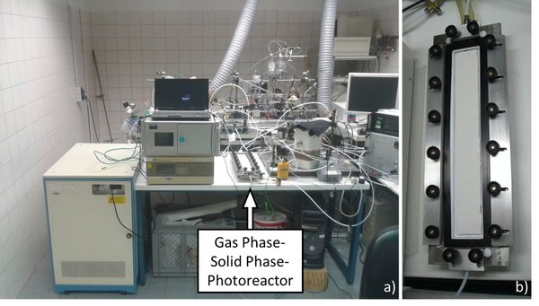
Figure 2: a) Picture of the complete experimental set-up in the lab, b) Gas phase – Solid phase - Photoreactor with a test object but without the light housing.
Gas phase – Aqueous phase – Photoreactor
To carry out experiments on the phase transfer gas phase - aqueous phase or aqueous phase gas phase, a cylindrical photoreactor was built at TROPOS with an empty volume of 5.7×10⁻⁴ m3 (0.06 m × 0.2 m). This results in a maximum aqueous phase surface area of 1.2 × 10⁻² m2 and a surface to volume ratio of 42.44 m-1 when half filled. Both experimental parameters can be varied based on the filling level. Depending on the experimental target, the aqueous phase is at rest or can be stirred during the experiment. The reactor is irradiated through a quartz glass window using an arc light source (e.g., xenon short arc lamp) in combination with various filtering systems (e.g., to simulate sunlight). The entire reactor is maintained at a constant temperature (e.g., 298K) using a thermostat. Figure 3 shows the gas phase - aqueous phase - photoreactor set up operating analogously to the gas phase - solid phase - photoreactor (see Figure 1). In addition to the sampling of the gas phase directly downstream of valve 2, the aqueous phase can be sampled and subsequently analyzed in parallel.
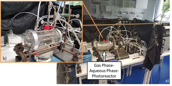
Figure 3: a) Picture of the complete experimental set-up in the lab, b) Zoom: Gas phase – Aqueous phase - Photoreactor half filled.
Aqueous phase – Photoreactor
A temperature-controlled aqueous phase photoreactor (see Figure 4 and Figure 5) with a volume of 300 mL is used to perform product studies related to the investigations of radical and non-radical oxidation processes of organic compounds in the aqueous particle phase. The photoreactor is irradiated by a solar simulator (LS0805-Q, LOT-Quantum Design) equipped with an air mass filter (AM1.5G). Depending on the experiment design, the photoreactor can alternatively be irradiated by an arc light source (LSH601, LOT Quantum Design) equipped with a xenon short arc lamp (450W, LSB541, LOT Quantum Design). The photoreactor contains an aqueous solution of radical precursor and the organic compound to be investigated. As the hydroxyl radical source, hydrogen peroxide is photolyzed in OH-driven oxidation experiments. The hydrogen peroxide concentration is adjusted to a concentration which yields to a steady state OH-radical concentration of around 1 × 10-13 mol L-1. Typical concentrations of the organic compound of these experiments are in the range of 1 × 10⁻³ mol L-1 to 1 × 10⁻⁶ mol L-1. Samples are taken manually at intervals of 5 up to 30 minutes.
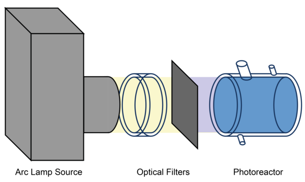
Figure 4. Schematic depiction of the experimental setup using the aqueous-phase photoreactor
Depending on the nature of potentially formed products, there is a variety of analytical systems to be used for qualitative and quantitative analysis, e.g., an UPLC-HRAM-MS (ultrahigh performance high-resolution accurate mass mass spectrometer). Additionally, several other analytical techniques, such as LC-MS/MS(Q-IMS-ToF), standard HPLC-QMS, GC-MS and CE-UV or CE-MS, are available to analyze target compounds, like carbonyls, small (C1-C4) carboxylic acids or even organosulfates.
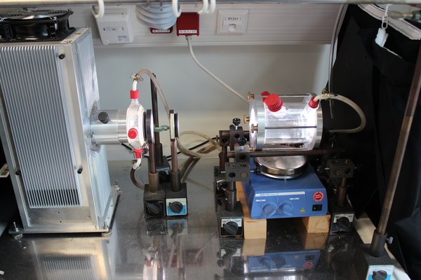
Figure 5: Picture of the experimental setup using the aqueous-phase photoreactor.
References
Mothes F., Ifang S., Gallus M., Golly B., Boréave A., Kurtenbach R., Kleffmann J., George C., Herrmann H. (2018) Bed flow photoreactor experiments to assess the photocatalytic nitrogen oxides abatement under simulated atmospheric conditions. Applied Catalysis B: Environmental 231, 161-172, doi: 10.1016/j.apcatb.2018.03.010.
Schindelka J., Iinuma Y., Hoffmann D., Herrmann H. (2013) Sulfate Radical-Initiated Formation of Isoprene-Derived Organosulfates in Atmospheric Aerosols. Faraday Discussions 165, 237-259, doi: 10.1039/c3fd00042g.
Rodigast M., Mutzel A., Schindelka J., Herrmann H. (2016) A new source of methylglyoxal in the aqueous phase. Atmos Chem Phys 16 (4), 2689-2702, doi: 10.5194/acp-16-2689-2016.
Otto T., Stieger B., Mettke P., Herrmann H. (2017) Tropospheric Aqueous-Phase Oxidation of Isoprene-Derived Dihydroxycarbonyl Compounds. The Journal of Physical Chemistry A 121 (34), 6460-6470, doi: 10.1021/acs.jpca.7b05879.
Prof. Dr. Hartmut Herrmann
Department Head